
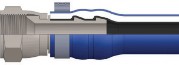
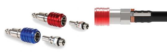
Fitting assembly with Boston EHW194 and EHW094 hose
Socketless, FD83 and UQD connectors
![]()
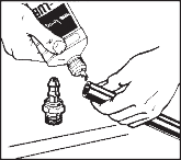
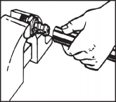
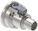
To Assemble Step 1
![]()
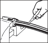
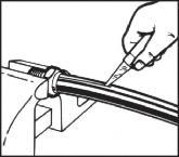
To Disassemble
Cut hose to required length with a sharp knife. Oil inside of hose and outside of SOCKETLESS nipple liberally (optional).
Low pressure service
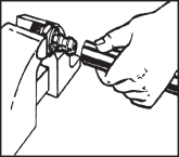
Push hose on fitting until hose end bottoms underneath protective cap as shown.
Slit hose lengthwise from protective cap to end of nipple.
Clamp location on hose tting
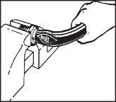
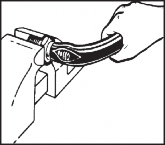
Bend hose, then snap hose off with a quick tug.
![]()
CLAMP INFORMATION for SOCKETLESS, FD83
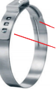
Ear width
T
d I
ongue-in-groove esign
nterlock
Dash size | Part number | Reference | Ear width | Band width | Size range |
mm (Inch) | mm (Inch) | mm (Inch) | |||
-04 | FF91764-162 | 016.0-706R | 8.0 (0.315) | 7.0 (0.276) | 13.5 - 16.0 (0.53 - 0.63) |
-06 | FF91764-198 | 019.8-706R | 10.0 (0.394) | 7.0 (0.276) | 16.6 - 19.8 (0.65 - 0.78) |
-08 | FF91764-241 | 024.1-706R | 10.0 (0.394) | 7.0 (0.276) | 20.9 - 24.1 (0.82 - 0.95) |
-10 | FF91764-271 | 027.1-706R | 10.0 (0.394) | 7.0 (0.276) | 23.9 - 27.1 (0.94 - 1.07) |
-12 | FF91764-316 | 031.6-706R | 10.0 (0.394) | 7.0 (0.276) | 28.4 - 31.6 (1.12 - 1.24) |
-16 | FF91764-396 | 039.6-706R | 10.0 (0.394) | 7.0 (0.276) | 36.4 - 39.6 (1.43 - 1.56) |
The use of clamp is dependent on the performance parameters of hose. Please refer to hose pressure ratings for when clamp is required.

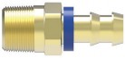
for quick disconnect coupling with Boston EHW094 & EHW194 hose
To Assemble Step 1
![]()
To Disassemble
Cut hose to required length with a sharp knife. Oil inside of hose and outside nipple liberally (optional).
Full-flow dual-interlock coupling
Push hose on coupling hose barb until hose end
touches the flat surface of the coupling body.
Slit hose lengthwise from edge of coupling body to end of the barb.
Bend hose, then snap hose off with a quick tug.
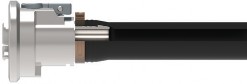
Clamp location
on hose tting
Clamp location on hose tting
![]()
Danfoss Power Solutions, Nordborgvej 81, 6430 Nordborg, Denmark, Tel. +45 74 88 22 22, Fax +45 74 65 25 80 www.danfoss.com, E-mail: info@danfoss.com
Any information, including, but not limited to information on selection of product, its application or use, product design, weight, dimensions, capacity or any other technical data in product manuals, catalogues descriptions, advertisements, etc. and whether made available in writing, orally, electronically, online or via download, shall be considered informative, and is only binding if and to the extent, explicit reference is made in a quotation or order con rmation. Danfoss cannot accept any responsibility for possible errors in catalogues, brochures, videos and other material. Danfoss reserves the right to alter its products without notice.
This also applies to products ordered but not delivered provided that such alterations can be made without changes to form, t or function of the product. All trademarks in this material are property of Danfoss A/S or Danfoss group companies. Danfoss and the Danfoss logo are trademarks of Danfoss A/S. All rights reserved.
© Danfoss | Power Solutions | November 2024 AN460864287876en-000103