Effective XXXX, 2025
Authors: Travis Gaskill - NVIDIA, Elizabeth Langer – CPC
Contributions to this Specification are made under the terms and conditions set forth in Modified Open Web Foundation Agreement 0.9 (OWFa 0.9). (As of October 16, 2024) (“Contribution License”) by:
Colder Products Company (CPC)
NVIDIA
Usage of this Specification is governed by the terms and conditions set forth in Modified OWFa 0.9 Final Specification Agreement (FSA) (As of October 16, 2024) (“Specification License”)
You can review the applicable Specification License(s) referenced above by the contributors to this Specification on the OCP website at https://www.opencompute.org/contributions/templates-agreements.
For actual executed copies of either agreement, please contact OCP directly.
NOTWITHSTANDING THE FOREGOING LICENSES, THIS SPECIFICATION IS PROVIDED BY OCP "AS IS" AND OCP EXPRESSLY DISCLAIMS ANY WARRANTIES (EXPRESS, IMPLIED, OR OTHERWISE), INCLUDING IMPLIED WARRANTIES OF MERCHANTABILITY, NON-INFRINGEMENT, FITNESS FOR A PARTICULAR PURPOSE, OR TITLE, RELATED TO THE SPECIFICATION. NOTICE IS HEREBY GIVEN, THAT OTHER RIGHTS NOT GRANTED AS SET FORTH ABOVE, INCLUDING WITHOUT LIMITATION, RIGHTS OF THIRD PARTIES WHO DID NOT EXECUTE THE ABOVE LICENSES, MAY BE IMPLICATED BY THE IMPLEMENTATION OF OR COMPLIANCE WITH THIS SPECIFICATION. OCP IS NOT RESPONSIBLE FOR IDENTIFYING RIGHTS FOR WHICH A LICENSE MAY BE REQUIRED IN ORDER TO IMPLEMENT THIS SPECIFICATION. THE ENTIRE RISK AS TO IMPLEMENTING OR OTHERWISE USING THE SPECIFICATION IS ASSUMED BY YOU. IN NO EVENT WILL OCP BE LIABLE TO YOU FOR ANY MONETARY DAMAGES WITH RESPECT TO ANY CLAIMS RELATED TO, OR ARISING OUT OF YOUR USE OF THIS SPECIFICATION, INCLUDING BUT NOT LIMITED TO ANY LIABILITY FOR LOST PROFITS OR ANY CONSEQUENTIAL, INCIDENTAL, INDIRECT, SPECIAL OR PUNITIVE DAMAGES OF ANY CHARACTER FROM ANY CAUSES OF ACTION OF ANY KIND WITH RESPECT TO THIS SPECIFICATION, WHETHER BASED ON BREACH OF CONTRACT, TORT (INCLUDING NEGLIGENCE), OR OTHERWISE, AND EVEN IF OCP HAS BEEN ADVISED OF THE POSSIBILITY OF SUCH DAMAGE.
Version 1 Author(s): Mark Sprenger (Intel), Jordan Johnson (Intel), Bret Henkel (Intel)
The Contributors of this Specification would like to acknowledge the following companies for their feedback:
AMD | Intel | CPC | Staubli | Parker |
Nvidia | Dell | CoolIT | Danfoss | Cejn |
This contribution complies with the OCP Tenets of Openness, Efficiency, Impact, Scale, and Sustainability.
This specification outlines the design and test criteria for any willing supplier to build and validate a supplier interchangeable fluid quick disconnect. The specification has been developed with input from suppliers and end users. The openness of the specification allows users to work with their preferred suppliers, and enables opportunities for liquid adoption in adjacent market segments.
This specification combines the previously separate specifications:
Universal Quick Disconnect (UQD) Specification, Revision 1.0
Universal Quick Disconnect Blind-Mate (UQDB) Specification, Revision 1.0
Consolidation of the specifications into a singular document streamlines accessibility and ease of adoption, while also ensuring parity of key performance parameters across the multiple sizes and configurations.
Through establishing and improving upon a supplier interchangeable fluid quick disconnect, this specification significantly lowers the barriers to adoption of liquid cooled compute, and enables liquid cooling at scale.
Universality of this specification enables a more robust and resilient global supply chain in support of scaling liquid cooling infrastructure for compute.
By lowering the barriers to mass adoption of liquid cooled computing, the world moves more quickly towards a more energy efficient mode of cooling and enables a more sustainable datacenter PUE compared to air cooling. By ensuring this version of the specification maintains a degree of backwards compatibility, reuse is encouraged and waste mitigated.
Date | Version # | Author | Description |
06Nov2024 | Draft | See Authors | Initial Version |
14Apr2025 | V2.0.1 | See Authors | UQD Workstream – alpha draft |
TERM | DEFINITION |
UQD | Universal Quick Disconnect - Handmate |
UQDB | Universal Quick Disconnect – Blindmate |
HANDMATE | Direct manual intervention required to couple and de-couple QD pair |
BLINDMATE | Indirect (blind, remote) coupling and de-coupling of QD pair via alternate mechanism(s) |
HYBRID | Blindmate coupling of UQD plug and UQDB socket |
PLUG | QD half with exterior mating geometry (AKA: male, insert) |
SOCKET | QD half with interior mating geometry (AKA: female, body) |
TERMINATION | QD end features to connect a tube, pipe or port |
COUPLED | State when plug and socket are fully engaged |
HARD-STOP | Condition in which the QD pair are coupled to the point of, and limited by, mechanical contact |
MAKE | Act of coupling the plug and socket to achieve coupled state |
BREAK | Act of de-coupling the plug and socket from the coupled state |
This document defines the technical specifications for the Universal Quick Disconnect (UQD) and Universal Quick Disconnect Blind-Mate (UQDB) used in non-combustible single-phase (water/glycol) systems for liquid cooling of electronics.
In liquid cooled systems, fluid is transported under pressure within a Technology Cooling System (TCS) fluid loop [1]. The IT equipment loop is joined to the TCS using a fluid connector.
QD DESCRIPTION | NOMINAL SIZE |
UQD02, UQDB02 | -02 (1/8”) |
UQD04, UQDB04 | -04 (1/4”) |
UQD06, UQDB06 | -06 (3/8”) |
UQD08, UQDB08 | -08 (1/2”) |


UQD Specification Version 2 is designed to be backwards compatible with the previously separate Version 1 Specifications for UQD and UQDB, and end user deployment assessment is encouraged. Risks and considerations for interchanging or co- deploying v1 and v2 components are outlined in the appendix (15.1).
Overall connected lengths of couple QD sets are reported as a “panel to panel” dimension, not including length associated with terminations (ie ORB stud or hosebarb length). Connected lengths are reference (driven) dimensions derived from component level dimensions and tolerances as outlined in Section 7.
Connected length of blindmate configurations are referenced in Figure 4. Mechanical hard-stop location for the UQDB is parallel face to face, and hybrid is conical surface of socket to tangent diameter of plug flange.
TOP: Hybrid Configuration | ||||
QD Size | MIN | Nominal | MAX | |
02 | 35.9 | 36.3 | 36.7 | |
04 | 43.6 | 44.1 | 44.5 | |
06 | 47.1 | 47.6 | 48.0 | |
08 | 51.1 | 51.6 | 52.0 | |
BOTTOM: UQDB Configuration | ||||
QD Size | MIN | Nominal | MAX | |
02 | 35.6 | 36.1 | 36.6 | |
04 | 43.8 | 44.3 | 44.8 | |
06 | 47.1 | 47.6 | 48.1 | |
08 | 50.9 | 51.4 | 51.9 | |
Connected length of handmate configurations are referenced in Figure 5, and defined as nominal reference value only. Socket length is defined as a maximum keep-in value (Table 2) and relative position of plug varies depending on the style of latching mechanism per supplier.
| UQD Configuration | |
QD Size | REF | |
02 | 56.1 | |
04 | 66.5 | |
06 | 71.5 | |
08 | 81.5 | |
Configuration specific features and dimensions are outlined below. Where no dimension is given, the geometry is left to the discretion of the supplier and should consider end user (datacenter environment) requirements for fit and function.
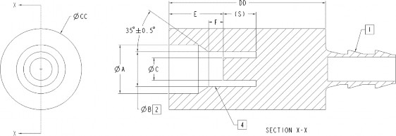
Physical features of the UQD socket shall conform to those outlined in Figure 6, and dimensions specified in Table 2.
Dimension ‘CC’ is a maximum keep-in-zone, which includes latching mechanism. Dimensions ‘DD’ is a maximum overall length
keep-in-zone. Reference dimension ‘S’ carries through to all socket/plug and UQD/UQDB configurations.
![]()
Dimension Tolerance | A | B | C | E | F | S | CC | DD | ||||
MIN | ± | 0.025 | ± | 0.025 | MIN | MAX | ± | 0.10 | REF | MAX | MAX | |
UQD02 | 11.25 | 6.71 | 3.63 | 12.8 | 13.7 | 3.3 | 8.0 | 25.0 | 50.0 | |||
UQD04 | 15.65 | 11.15 | 7.14 | 16.6 | 18.1 | 4.7 | 11.3 | 30.0 | 60.0 | |||
UQD06 | 18.85 | 14.38 | 9.47 | 17.3 | 18.8 | 5.4 | 14.3 | 35.0 | 65.0 | |||
UQD08 | 22.05 | 17.56 | 10.75 | 18.5 | 20.0 | 6.6 | 17.3 | 40.0 | 75.0 | |||
NOTE 1 | Termination location - see Table 6 for details | |||||||||||
NOTE 2 | Sealing / Interoperability surface – machine to 32Ra MAX | |||||||||||
NOTE 4 | Seal gland(s) located on this surface - QD supplier defined | |||||||||||


![]()
![]()
Dimension | G | H | J | L | M | N | P | Q | R | AA | BB | GG | |
Tolerance | ±0.025 | ±0.025 | MIN | ±0.025 | MIN | MAX | ±0.1 | ±0.06 | ±0.3 | MAX | ±0.10 | ±0.10 | MAX |
UQD02 | 11.0 | 6.65 | 21.0 | 3.73 | 2.4 | 3.0 | 15.5 | 14.8 | 19.4 | 6.8 | 14.10 | 27.0 | 19.8 |
UQD04 | 15.4 | 11.07 | 29.0 | 7.24 | 3.0 | 3.8 | 21.5 | 20.7 | 26.5 | 11.2 | 19.20 | 35.4 | 16.5 |
UQD06 | 18.6 | 14.30 | 32.5 | 9.75 | 3.5 | 4.8 | 25.0 | 24.2 | 30.0 | 14.2 | 22.67 | 38.9 | 25.5 |
UQD08 | 21.8 | 17.48 | 36.5 | 11.17 | 3.8 | 5.8 | 29.0 | 28.2 | 34.0 | 17.4 | 26.69 | 42.9 | 31.5 |
NOTE 1 | Termination location - see Table 6 for details | ||||||||||||
NOTE 2 | Sealing / Interoperability surface - machine to 32Ra MAX | ||||||||||||
NOTE 3 | Hex feature for installation to be on this surface - see Table 6 for details | ||||||||||||
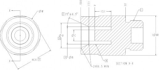
Physical features of the UQDB socket shall conform to the features outlined in Figure 8, and dimensions specified in Table 4.
Dimension | B | C | T | U | V | W | FF |
Tolerance | ±0.025 | ±0.025 | REF | ±0.1 | ±0.3 | MAX | ±0.1 |
UQD02 | 6.71 | 3.63 | 4.81 | 11.2 | 7.11 | 21.4 | 23.62 |
UQD04 | 11.15 | 7.14 | 5.20 | 16.0 | 8.90 | 25.4 | 28.50 |
UQD06 | 14.38 | 9.47 | 4.95 | 19.0 | 9.35 | 28.4 | 31.75 |
UQD08 | 17.56 | 10.75 | 4.76 | 22.0 | 10.36 | 31.4 | 35.56 |
NOTE 1 | Termination location - see Table 6 for details | ||||||
NOTE 2 | Sealing / Interoperability surface - machine to 32Ra MAX | ||||||
NOTE 3 | Hex feature for installation to be on this surface - see Table 6 for details | ||||||
NOTE 4 | Seal gland(s) located on this surface - QD supplier defined | ||||||
NOTE 6 | Dimension to theoretical sharp corner (TSC) | ||||||
Physical features of the UQDB socket shall conform to the features outlined in Figure 9, and dimensions specified in Table 5.

Dimension | H | K | L | M | X | Y | W | SA | |
Tolerance | ±0.025 | ±0.3 | ±0.025 | MIN | MAX | ±0.1 | ±0.3 | MAX | +0.30 / -0.00 |
UQD02 | 6.65 | 11.0 | 3.73 | 2.4 | 3.0 | 27.0 | 14.50 | 21.4 | 1.00 |
UQD04 | 11.07 | 16.1 | 7.24 | 3.0 | 3.8 | 35.4 | 19.60 | 25.4 | 1.00 |
UQD06 | 14.30 | 19.6 | 9.75 | 3.5 | 4.8 | 38.9 | 23.10 | 28.4 | 1.00 |
UQD08 | 17.48 | 23.6 | 11.17 | 3.8 | 5.8 | 42.9 | 27.10 | 31.4 | 1.00 |
NOTE 1 | Termination location - see Table 6 for details | ||||||||
NOTE 2 | Sealing / Interoperability surface - machine to 32Ra MAX | ||||||||
NOTE 3 | Hex feature for installation to be on this surface - see Table 6 for details | ||||||||
NOTE 5 | QD supplier defined area, keep-in-zone bounded by dimension 'Y', 'K' and MIN angle | ||||||||
NOTE 7 | Self-alignment (SA) shall be incorporated into plug assembly, dimension is a radial allowance | ||||||||
Terminations are subject to the performance requirements specified in this document. Minimum product offering should reflect the terminations outlined in the table below. For barbed terminations, barb design and number of barbs are at the discretion of the QD supplier. Additional termination offerings are at the discretion of the QD supplier.
Description | Stud End ISO11926-3 [2]1 | |||
QD Size | 02 | 04 | 06 | 08 |
Stud Size | ORB-04 | ORB-06 | ORB-08 | ORB-10 |
Reference Thread | 7/16-20 UNF-2A | 9/16-18 UNF-2A | 3/4-16 UNF-2A | 7/8-14 UNF-2A |
Recommended Hex - UQD | 14mm | 17mm | 22mm | 27mm |
Recommended Hex - UQDB | 19mm | 24mm | 27mm | 30mm |
Suggested Torque2 | 9 Nm | 15 Nm | 25 Nm | 30 Nm |
1Reference ISO11926-1 [x] for mating port geometry 2Torque values should consider mating geometry, material, lubrication and any other application specific variables | ||||
![]()
Description | Stud End ISO11926-3 [2]1 | |||
QD Size | 02 | 04 | 06 | 08 |
Stud Size | ORB-06 | ORB-08 | ORB-10 | ORB-12 |
Reference Thread | 9/16-18 UNF-2A | 3/4-16 UNF-2A | 7/8-14 UNF-2A | 1-1/16-12 UNF-2A |
Recommended Hex | 17mm | 19mm | 24mm | 27mm |
Suggested Torque2 | 15 Nm | 25 Nm | 30 Nm | 48 Nm |
1Reference ISO11926-1 [3] for mating port geometry 2Torque values should consider mating geometry, material, lubrication and any other application specific variables | ||||
Description | Hosebarb (Push-Lock) | |||
QD Size | 02 | 04 | 06 | 08 |
Hosebarb Size | 1/4" HB | 3/8" HB | 1/2" HB | 5/8" HB |
1Hosebarb intended for use with reinforced EPDM hose, consult QD supplier/Tube supplier for additional information and installation guidance | ||||
To comply with this document, the product shall meet or exceed the performance requirements listed in Table 7. Flow rating and performance are related to water unless otherwise specified.
Flow Rating –
MIN
{A,B}
{A,B}
{A,B}
{A,B}
MAX
{A,B}
{A,B}
{A,B}
{A,B}
Coupling Force @0psi
Notes
1 Limiting factor related to mitigating seal washout during coupling cycles under flow
2 Applies to UQDB only (ie valving), the locking mechanism of handmate socket is expected to marginally increase the force to connect
10 years
-
Service Life
5 years
-
Storage Life (from T0)
[10°C, 65°C] / [50°F, 149°F]
[MIN, MAX]
Temperature Range - Operating
[-40°C, 70°C] / [-40°F, 158°F]
[MIN, MAX]
Temperature Range - Shipping
0.07
0.04
0.03
0.02
mL
Fluid Loss per Cycle @0psi - Maximum
# cycles
Coupling Cycles - Minimum
20
20
15
12
lbf
135.0
90.0
65.0
55.0
N
3.5
1.9
1.1
0.3
-
Cv Reference
Flow Performance - Pressure Drop Polynomials {A,B}
4.7
3.0
1.7
0.6
GPM
17.79
11.36
6.44
2.27
L/min
20.68 bar(g) / 300 psi(g)
-
Pressure - Minimum Proof
6.89 bar(g) / 100 psi(g)
-
Pressure - Maximum Operating
1000
- Maximum2
Maximum1
![]()
![]()
![]()
![]()
![]()
![]()
![]()
![]()
![]()
The tests in this section are reflective of the requirements in Table 7. The tests are broken down into the following groups:
QD Property Tests
Thermal / Mechanical Cycling Tests


Each test shall be conducted and the test data collated in a test report. A “QD Validation Report Template” is provided with
this specification as the preferred template for reporting. The test report shall be provided to customers upon request. All helium leak tests conducted shall be in accordance with ASTM E493.
In accordance with ISO 18869 [4], the required sample size per test is 5, at minimum. In accordance with ISO 18869:2017
Section 6.3, the instruments must meet certain accuracy requirements.
Test Description | Conduct a burst pressure test on the plug, socket, and mated pair. |
Test Position | Fully mated (UQD/UQDB pair) and disconnected (plug/socket) |
Test Pressure | Test to failure, or pressure 3x minimum proof pressure – whichever is lower |
Specific to UQDB | Test should be conducted at the fully mated, hard-stop condition |
Acceptance Criteria |
Test Description | Conduct the test according to ISO 18869 Section 12 |
Test Fluid | Water |
It is recommended to minimize coupling and decoupling forces for both UQD and UQDB applications. In addition, latching mechanisms shall provide visual, tactile, and or audible feedback to users. UQD pairs shall lock together in the coupled condition.
Test Description | Conduct the test according to ISO 18869 Section 7. Repeat the test for a total of five times per sample. Use the maximum force found per test and average the results from all the tests and all the samples to determine the connect force. Report the average (of the maximums) in the test report. Unless otherwise requested, the test shall be conducted while fully aligned radially and angularly. |
Test Temperature | Ambient |
Test Pressures | Conduct the test at 3 pressure levels: 0/2.76/6.89 bar(g) (0/40/100 psi(g)) |
Test Fluid | Air or water |
Connection Speed | 40 mm/s |
Specific to UQDB | Conduct the test at maximum radial misalignment, resetting the misalignment to maximum after each cycle. |
Test Description |
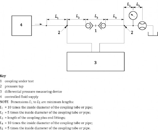
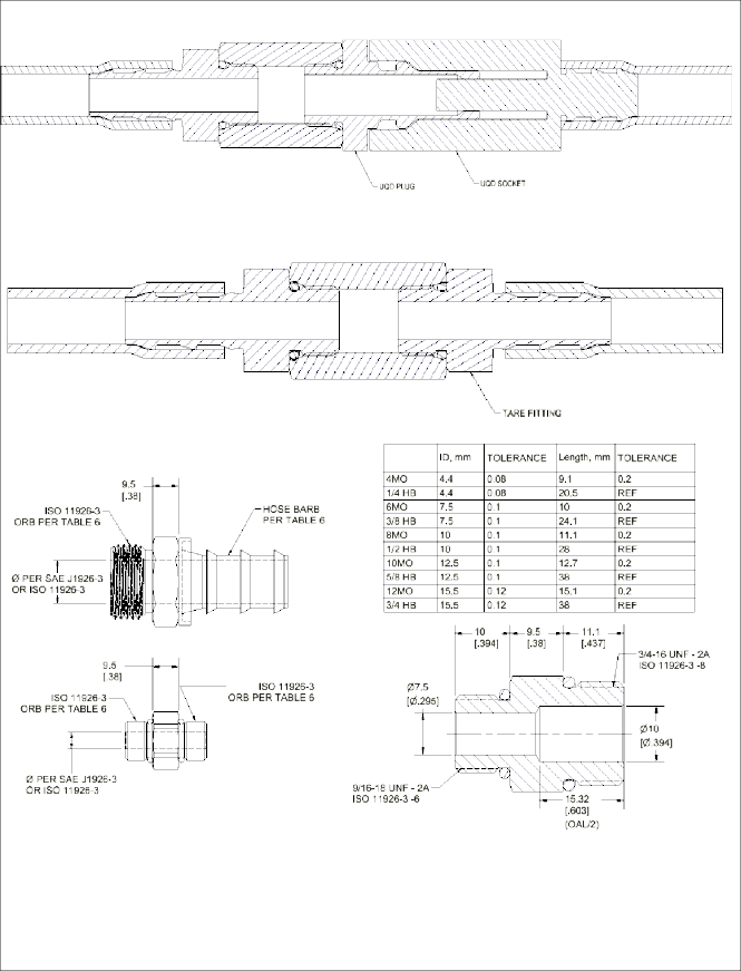
Conduct the test according to ISO 18869, Section 13 except as indicated below.
The test apparatus shall use hose or tubing of inside diameter corresponding to the default hose diameter per Table 6 of this standard (for example, UQD04 has 3/8” barb, therefore all UQD/UQDB04 should be tested with .375”±10% ID |
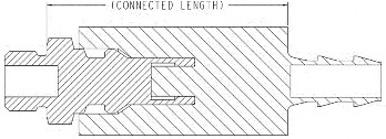
hose/tube). The connections to the QD shall be made with minimal adapter fittings, example as shown in the image below. This image represents the section from L2 through L4 of ISO 18869 Figure 7 as shown above.
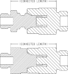
ISO 18869, Section 13.3 – Remove the test coupling from the test apparatus and connect the tubes or hoses using a connector per the images below. All hose, tubing, or fittings connected between pressure taps (2) and coupling under test (1) shall be the same in test and tare setup.
ISO 18869, Section 13.4 – Test fluid used shall be 25% propylene glycol and 75% water, with or without additives, and the test shall be performed at approximately 25±5°C.
ISO 18869, Section 13.5 – Subtract the pressure drop values collected in section 13.3 from those collected in 13.2. Graphically plot the net pressure drop for each flow direction. Calculate the best fit polynomial and report the curve fit equation for the average pressure drop (n=5 minimum) in each flow direction as well as pressure drop at 100% and 150% of rated flow.
ISO 18869, Section 13.6 – Report pressure drop in both flow directions.
Test Temperature | 25±5°C1 |
Test Fluid | PG25 |
Test Flowrates | The 100% rated flowrate is defined by the Flow Rating parameter herein the specification. Select at least six flow rates from 25 % to 150 % of the rated flow, including 100 % of rated flow. |
Specific to UQDB | Test should be conducted at the fully mated, hard-stop condition |
Reported Value | Pressure drop vs. flowrate should be reported using a best fit line with an equation of the form: 𝑑𝑃(𝑄) = 𝐴 ⋅ 𝑄2 + 𝐵 ⋅ 𝑄. Report the coefficients A and B when using the units [L/min] for flowrate and [psi] for pressure. Coefficients for different units may be provided as supplementary information. |
9.1.5. Seal Washout
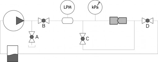
The Seal Washout test is conducted to ensure that the seal geometry of the QD can withstand connection / disconnection under high pressure / flowrate conditions without washing the plug / socket valve seal out of its gland, creating a leak. This test is meant to recreate the real world scenario of connecting / disconnecting a filled server into a filled TCS loop.
Test Description | Using a test setup similar to the below diagram, conduct the following: Setup Process:
|
Number of Cycles | 20, each direction (plug to socket / socket to plug) |
Test Flowrate | 2x the Maximum Flow Rating for the QD |
Test Temperature | 60°C |
Test Pressure | 6.9 bar(g) (100 psi(g)) |
Test Fluid | Water or PG25 |
Connection Speed | 40mm/s ±10mm/s |
Before connection: Close valve C and adjust relief valve A. Supply side has fluid with a static pressure equal to the Maximum Operating Pressure.
Fully Connected: Adjust valves B & D to achieve test flowrate Test Process:
When the QDs are disconnected: Check the pressure meter, ensuring the static pressure is at the Test Pressure
When the QDs are connected: Check the flow meter, ensuring the flowrate is at the Test Flowrate
Conducting the test: Connect and disconnect the coupling according to the number of cycles, checking for leakage or seal washout after each cycle.
![]()
1 The test temperature of 25±5°C is a known discrepancy to the OCP BMQC Specification’s test temperature of 40°C. 25°C was chosen to
simplify the test setup with the understanding of slight performance differences at higher temperature due to viscosity and specific gravity.
Acceptance Criteria | No leakage or seal washout |
Test Description | Helium leak test each sample before the test. Conduct a thermal cycling test with air. After testing, conduct helium leak tests on all samples. |
Test Position | Fully Connected (UQD/UQDB) and disconnected (plug/socket) |
Test Temperature | -40°C for 72H and +75°C for 72H and back to room temperature |
Temperature Transition Rate | 10°C/min |
Test Fluid | Air |
Specific to UQDB | Test should be conducted at the fully mated, hard-stop condition |
Acceptance Criteria | No visible leakage. After testing, helium leak rate <= 1x10⁻⁵ mbar-L/s |
Test Description | Conduct a hydrostatic pressure test at 6.9 bar(g) (100 psi(g)) on each sample before the test. Conduct a thermal cycling test with the test fluid. After testing, conduct a hydrostatic pressure test. |
Test Position | Connected with nominal engagement (UQD/UQDB) and disconnected (plug/socket) |
Test Temperature | 17°C for 72H and +65°C for 72H and back to room temperature |
Temperature Transition Rate | 10°C/min |
Test Pressure | 6.9 bar(g) (100 psi(g)) at test temperature |
Test Fluid | Water or PG25 |
Acceptance Criteria | No visible leakage. After testing, conduct a hydrostatic pressure test at 6.9 bar(g) (100 psi(g)) |
Test Description | Cycle the UQD/UQDB. For UQD, the latch must be actuated each cycle. After testing, conduct a hydrostatic pressure test. | |
Number of Cycles | 5000 | |
Connection Speed | 40 mm/s | |
Test Temperature | TBD | |
Test Pressure | 2.75 bar(g) (40 psi(g)) | |
Test Fluid | Water or PG25 | |
Acceptance Criteria | After testing, no visible leakage. After testing, conduct a hydrostatic pressure test at 6.9 bar(g) (100 psi(g)) | |
Suppliers shall cross-validate their parts with a minimum of 3 other suppliers. In accordance with the OCP tenet of Openness, UQD suppliers shall make their UQDs available to other UQD suppliers upon request for cross-validation purposes. Likewise, the requesting supplier shall make available their UQDs at the time of request. UQD Suppliers shall publish the supplier list with which their QDs have successfully passed cross-validation testing. The cross-validation test reports shall be made available to customers upon request.
The required cross-validation tests, shown in Figure 12, are a subset of the QD Property Tests. These tests are considered critical to ensuring the interoperation of one supplier’s QDs with those of a different supplier. The tests may be run in parallel or series. In accordance with ISO 18869, the required sample size per test is 5, at minimum. In accordance with ISO 18869:2017 Section 6.3, the instruments must meet certain accuracy requirements.

Identification as UQD / UQDB and nominal size are required per Table 8. Marking can be positioned per supplier’s discretion
on any visual external surface of the plug and socket.
QD Size | UQD | UQDB |
02 | UQD02 v2 | UQDB02 v2 |
04 | UQD04 v2 | UQDB04 v2 |
06 | UQD06 v2 | UQDB06 v2 |
08 | UQD08 v2 | UQDB08 v2 |
Within digital or printed catalogs, suppliers shall identify products meeting these requirements as “Dimensional & performance requirements conform to OCP UQD Specification v2.0”.
Supplier to ensure materials used in the construction of UQD / UQDB are compatible with the Acceptable Wetted Materials as identified in OCP’s “Guidelines for Using Water-Based Transfer Fluids in Single-Phase Cold Plate-Based Liquid-Cooled Racks” as well as “Guidelines for Using Propylene Glycol Based Heat Transfer Fluids in Single Phase Cold Plate-Based Liquid Cooled Racks”.
Furthermore, the UQD / UQDB Plug and Socket must adhere to the following materials in Table 9. This is to ensure similar material hardness on components that see forceful contact.
Location | Material Requirement |
UQD / UQDB Plug External Tip / Shaft | SUS 303 / 304 / 304L / 316 / 316L |
UQD / UQDB Cone and Guide in Area | SUS 303 / 304 / 304L / 316 / 316L |
Safety & Regulatory Requirements
Supplier to ensure relevant regulatory and safety standards in industry are adhered to.
[1] | ISO Standard 18869, "Hydraulic fluid power - Test methods for couplings actuated with or without tools," 2017. |
[2] | ISO Standard 11926-3, "Connections for general use and fluid power - Ports and stud ends with ISO 725 threads and O-ring sealing - Part 3: Light duty (L series) stud ends," 1995. |
[3] | ISO Standard 11926-1, "Connections for general use and fluid power - Ports and stud ends with ISO 725 threads and O-ring sealing - Part 1: Ports with O-ring seal in truncated housing," 1995. |
[4] | OCP Guideline, "Using Propylene Glycol-Based Heat Transfer Fluids in Single-Phase Cold Plate-Based Liquid Cooled Racks," 2025. |
[5] | OCP Guideline, "Using Water-Based Transfer Fluids in Single-Phase Cold Plate-Based Liquid-Cooled Racks". |
Reference considerations for evaluating co-deployment of v1 and v2 UQDs in application.
Version 1 (V1) | Version 2 (V2) | Interchange Consideration |
UQD & UQDB plug end condition undefined | UQD & UQDB plug end conditions defined | V1 plug end with minimal/no chamfer may damage V1 & V2 socket seal(s) |
UQD plug & socket overall length undefined | UQD plug & socket overall length defined | V1 lengths may vary from standard V2 length, retain V1 panel/space |
UQD plug & socket outer diameter undefined | UQD plug & socket maximum outer diameter defined | V1 outer diameter may vary from standard V2 outer diameter, retain v1 pitch/space |
Performance requirement of ‘Minimum Cv’ | Performance requirement adjusted to ‘Minimum & Maximum’ PQ curves (Cv REF), nominal values increased over v1 | V1 pressure drop across QD valves may be higher than V2 (V1 Cv lower than V2) |
Minimum ‘S’ valve stroke defined | Increase minimum ‘S’ valve stroke to account for tolerances | V1 QD sets may not fully couple due to tolerance stacks of internal valving (issue present in V1) |
UQDB minimum & nominal engagement stroke defined, requiring full flow in “under coupled” condition | Tolerance loops do not support minimum engagement requirement without further changes, remove from specification and replace with guidance to ensure full coupling at hard-stop | V1 systems without built in tolerance compliance may see coupling panel distance and flow variation |
Quick Disconnect Validation Report Checklist | ||||||
QD Supplier | Date of Report | |||||
QD Type (Plug & Socket) | ||||||
Mechanical Spec | OCP UQD Specification v2 | |||||
Test Spec | OCP UQD Specification v2 | |||||
Supplier Validation Tests | ||||||
Test # | Test Type | Unit of Measure | Specification | Result | Notes | |
9.1.1. | Burst Pressure | |||||
9.1.2. | Fluid Loss | |||||
9.1.3. | Force to Connect | |||||
9.1.4. | Pressure Drop | |||||
9.1.5 | Seal Washout - Operational Test | |||||
9.2.1. | Non-Operational Temperature Cycling | |||||
9.2.2. | Operational Temperature Cycling | |||||
9.2.3. | Mechanical Cycling | |||||
Additional Notes: | ||||||
Supplier Cross-Validation Report Checklist | ||||||
Main QD Supplier | Date of Report | |||||
Cross-Validation QD Supplier | ||||||
QD Type (Plug & Socket) | ||||||
Mechanical Spec | OCP UQD Specification v2 | |||||
Test Spec | OCP UQD Specification v2 | |||||
Supplier Cross-Validation Tests | ||||||
Test # | Test Type | Unit of Measure | Specification | Result | Notes | |
9.1.2. | Fluid Loss | |||||
9.1.3. | Force to Connect | |||||
9.1.4. | Pressure Drop | |||||
9.1.5 | Seal Washout - Operational Test | |||||
Test ID | 9.1.1. | ||||
Test Description | Burst Pressure | ||||
Sample ID | |||||
Condition | 1 | 2 | 3 | 4 | 5 |
Plug | P/F | P/F | P/F | P/F | P/F |
Socket | P/F | P/F | P/F | P/F | P/F |
Mated | P/F | P/F | P/F | P/F | P/F |
Test ID | 9.1.2. | ||||||
Test Description | Fluid Loss | ||||||
Sample ID | Avg. over Samples | Pass / Fail / NA | |||||
1 | 2 | 3 | 4 | 5 | |||
Fluid level prior to test (mL) | |||||||
Fluid level after test (mL) | |||||||
# of Connections | |||||||
Fluid loss (mL/cycle) | |||||||
Test ID | 9.1.3. | |||||||
Test Description | Force to Connect | |||||||
Sample ID | ||||||||
Pressure (bar (g)) | Test | 1 | 2 | 3 | 4 | 5 | Avg. over Samples | Pass / Fail / NA |
0 | 1 | |||||||
0 | 2 | |||||||
0 | 3 | |||||||
0 | 4 | |||||||
0 | 5 | |||||||
0 | Avg. | |||||||
2.76 | 1 | |||||||
2.76 | 2 | |||||||
2.76 | 3 | |||||||
2.76 | 4 | |||||||
2.76 | 5 | |||||||
2.76 | Avg. | |||||||
6.89 | 1 | |||||||
6.89 | 2 | |||||||
6.89 | 3 | |||||||
6.89 | 4 | |||||||
6.89 | 5 | |||||||
6.89 | Avg. | |||||||
Test ID | 9.1.4. | ||||||
Test Description | Pressure Drop | ||||||
Flowrate (GPM) | Flow Direction (S-P / P-S) | Sample Pair ID | Avg. across Samples | ||||
1 | 2 | 3 | 4 | 5 | |||
Pressure Drop (psi(g)) | |||||||
Flowrate 1 | S-P | ||||||
Flowrate 2 | S-P | ||||||
Flowrate 3 | S-P | ||||||
Flowrate 4 | S-P | ||||||
Flowrate 5 | S-P | ||||||
Flowrate 6 | S-P | ||||||
Flowrate 1 | P-S | ||||||
Flowrate 2 | P-S | ||||||
Flowrate 3 | P-S | ||||||
Flowrate 4 | P-S | ||||||
Flowrate 5 | P-S | ||||||
Flowrate 6 | P-S | ||||||
dP at Flow Rating | Curve Fit Quadratic Coefficients (of the form: dP = A*Q^2+B*Q) | ||||||
Flow Direction (S-P / P-S) | dP at 100% rated flow (psi(g)) | dP at 150% rated flow (psi(g)) | A | B | Within Spec? (Y/N) | ||
S-P | |||||||
P-S | |||||||
Test ID | 9.1.5. | ||||
Test Description | Seal Washout | ||||
Subtest | 9.1.5.1 - Operational Test | ||||
Sample ID | |||||
Flow Direction (S-P / P-S) | 1 | 2 | 3 | 4 | 5 |
S-P | P/F | P/F | P/F | P/F | P/F |
P-S | P/F | P/F | P/F | P/F | P/F |
Test ID | 9.2. | ||||
Test Description | Thermal / Mechanical Cycling Tests | ||||
Subtest | 9.2.1. - Non-Operational Temperature Cycling | ||||
Sample ID | |||||
Condition | 1 | 2 | 3 | 4 | 5 |
Plug | P/F | P/F | P/F | P/F | P/F |
Socket | P/F | P/F | P/F | P/F | P/F |
Mated | P/F | P/F | P/F | P/F | P/F |
Subtest | 9.2.1. - Operational Temperature Cycling | ||||
Sample ID | |||||
Condition | 1 | 2 | 3 | 4 | 5 |
Plug | P/F | P/F | P/F | P/F | P/F |
Socket | P/F | P/F | P/F | P/F | P/F |
Mated | P/F | P/F | P/F | P/F | P/F |
Subtest | 9.2.3. - Mechanical Cycling | ||||
Sample ID | |||||
Condition | 1 | 2 | 3 | 4 | 5 |
Plug | P/F | P/F | P/F | P/F | P/F |
Socket | P/F | P/F | P/F | P/F | P/F |