|
|
|
|
NVIDIA Q3450-LD Liquid-Cooling System
Copyright 2025, NVIDIA. Last updated on Dec 2, 2025
Overview
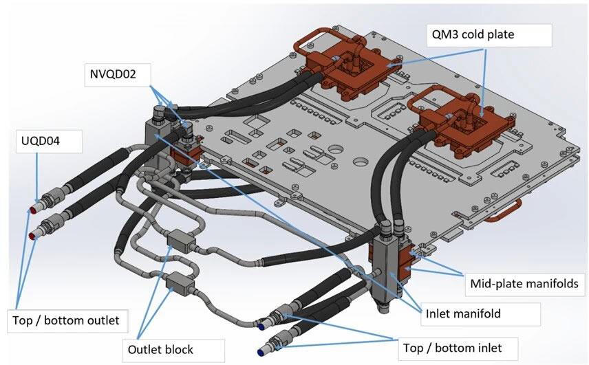
The Q3450-LD liquid-cooling system features two parallel cooling loops operating concurrently. Liquid enters via two separate inlet ports and exits through two outlet ports. Fluid enters through two inlet manifolds on the left and right sides of the system's rear part, each splitting into two paths: one to the upper QM3 cold plate (left/right) and one to the lower QM3 cold plate (left/right), forming two parallel loops. After cooling the QM3 cold plates, the fluid flows to the mid-plate manifolds, then cools the switch board components via upper and lower loops (left/right). Unlike the inlet lines, which are split by side (left/right), the outlet lines are grouped by level: upper sections from both sides converge at the top outlet block, and lower sections at the bottom outlet block. The combined flow exits through ports on the left side.
Liquid-Cooling System 3D View
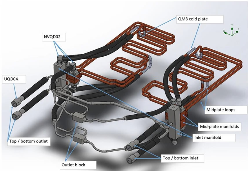
Liquid-Cooling System 3D View with Visible Mid-Plate Loops
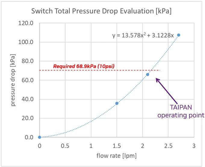
The system operates at [4.3 LPM, 10 PSI]. The below curve applies to PG25 at 45��C (see Specifications). As the system has two parallel inlet/outlet ports, the flow rate at the operating condition is half the total switch liquid flow rate.
Deployment
Inserting the Switch Module (Liquid System Related)
The switch modules are pre-filled with nitrogen in the cooling system, pressurized to at least 1 psi. If the pressure is below 1 psi, perform a "Pressure Hold": refill to 50 psi with N2, wait 12 hours, and verify that the pressure remains above 48 psi to pass. Positive nitrogen pressure prevents humidity or dust ingress.
- Before insertion, release the gas using the open-ended hose from the maintenance kit.
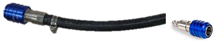
- Connect the hose to either of the two FRU hoses to automatically expel the gas.
- Disconnect the hose once the gas is fully released, then proceed with module insertion.
Warning
Failure to fully flood the cooling system with liquid before powering-on may cause significant damage and void the warranty.
Liquid-Cooling System Related Actions
Pressure Check of Nitrogen-Filled Components
Purpose:
-
Confirm that cold plate assemblies, switch trays, and manifolds retain supplier-filled N2 pressure, ensuring no leaks during transit.
Required Hardware:
Process
Pass/Fail Criteria
-
Must retain ��1 psi.
-
If the pressure is lower than 1 psi, please perform a "Pressure Hold" test as follows:
-
Failures are returned to the supplier.
PG25 Fill
Purpose:
Required Hardware:
-
For vacuum fill: Vacuum pump, liquid trap
-
For positive pressure fill: Fill pump
-
25-micron filter on the supply side (for both the component and the rack)
Process
-
Vacuum Fill:
-
Pull vacuum on the assembly from the outlet quick disconnect (QD).
-
Fill the fluid from the inlet QD.
-
Stop filling when the fluid enters the liquid trap.
-
Vacuum specification: 5 kPa or less.
-
Positive Pressure Fill:
Pass/Fail Criteria
Caveats:
-
If using a positive pressure pump with circulation, ensure a 25-micron filter is installed on the supply side.
-
If the assembly is complex with multiple fluidic elevations or high points, vacuum filling is preferred.
-
Expected Cycle Time: 2�C3 minutes.
RMA
Temperature Sensitivity of Fully Filled Liquid Systems |
TPU Exposure Risks |
Recommended Shipment Processes |
Storage Time Limitation |
Fully filled liquid cooling systems are susceptible to temperature fluctuations during transportation or storage, potentially causing volume changes and deformation damage. |
Prolonged storage of fully filled PG25 liquid systems can damage TPU internal LC connections. To prevent this, specific shipment processes must be followed. |
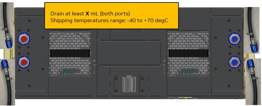
Partial Drainage Shipment
-
Remove the Taipan from system manifold and drain its cooling loop (via gravity or pumping).
-
Vent the unit during drainage by connecting one UQD side to the drain and the other as a vent.
-
Ensure at least XXX ml are drained (TBD).
-
This process supports shipment temperatures from -40��C to 70��C.
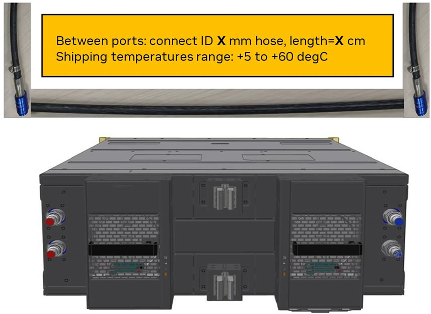
Alternate Wet Tray Shipment
-
Connect an external hose (XXX diameter, XXX cm length �C TBD) between the two UQDs of the Taipan to provide an expansion buffer.
-
This method is suitable for transportation temperatures between 5��C and 60��C.
|
Regardless of the chosen shipment method, limit storage time to a maximum of 45 days before arrival at Nvidia RMA Labs. |
RMA with Liquid-Drained System
RMA with Liquid-Filled System
Specifications
Parameter |
Value |
Minimal liquid inlet temperature |
17 ��C |
Maximal liquid inlet temperature |
45 ��C |
Maximal liquid return temperature |
55 ��C |
Target sustained system flow rate |
4.3 l/min |
Normal pressure |
2.4 Bar |
Max operating/shipment pressure (gauge)
abnormal / single fault |
5 Bar |
Burst pressure (gauge) |
15 Bar |
Liquid pressure drop |
10 PSI |
Coolant |
Recochem OAT PG25 |
Connection type |
Tray side (male): UQD04
Rack manifold (female) side: UQDB04 |
Filtration Requirement |
Support [25um: 50um] |
Liquid volume |
410 mL |
Ambient Temperature |
Operational: 5��C to 40��C for altitude: 0-900 m
Above 900 m, derate 1 ��C / 175 m (do not install unit above 3,050 m in any case).
Non-Operational: 5��C to 60��C |
Humidity |
Operational: 10-85% non-condensing
Non-Operational: 10-90% non-condensing |
Altitude |
Operational: 0-3,050 meters
Non-operational: 0-12,000 m |
Copyright 2025, NVIDIA. Last updated on Dec 2, 2025

About Beijing Hansen
Beijing Hansen Fluid Technology Co., Ltd. is an authorized distributor of Danfoss China, specializing in the data center industry. Our product portfolio includes Danfoss FD83 full-flow double-interlock liquid cooling quick-disconnect couplings (equipped with interlocking ball valves); universal liquid cooling quick-disconnect couplings UQD & UQDB; OCP ORV3 blind-mate quick-disconnect couplings BMQC; EHW194 EPDM liquid cooling hoses; solenoid valves; and pressure/temperature sensors. Amid the convergence of strategic trends such as artificial intelligence (AI), China��s national digital economy, the ��Eastern Data and Western Computing�� initiative, the ��dual carbon�� goals, and new infrastructure development, we are committed to building a high-caliber, experienced team of liquid cooling engineers. We deliver exceptional engineering design, robust customer service, and support global large-scale deployment.
Products: Danfoss liquid cooling fluid connectors, EPDM hoses, solenoid valves, pressure/temperature sensors, and manifolds.
Development Plan:Our goal is to become a leading provider of liquid cooling infrastructure solutions for data centers, with professional R&D, design, and manufacturing capabilities for cooling distribution units (CDUs), secondary fluid networks (SFNs), and manifolds.
Data center liquid cooling Solutions ~ One partner, every solution :
- Source line solutions: Danfoss Hansen FD83 Series Full-fow dual-interlock coupling
- Inner rack solutions: Newly engineered universal liquid cooling quick connectors UQD & UQDB compliant with OCP standards; OCP ORV3 blind-mate quick-disconnect connectors BMQC, supporting mass delivery on a global scale.
- Inner rack solutions: Danfoss Hansen MQD and MQDB Liquid Cooling Quick-Disconnect Connectors: MQD02 (H20); MQD03 (Blackwell B300 GB300); MQD04; MQDB03 and MQDB04.
- For application scenarios including Manifold/node, CDU/main loop in rack-mounted servers, manual and fully automatic quick connectors with different calibers and locking mechanisms are available.
- For blade racks requiring high availability and high density, blind-mate connectors with floating function and automatic misalignment correction are offered to enable precise docking in confined spaces.
- Liquid Cooling Hoses: EHW194 EPDM (Ethylene Propylene Diene Monomer) hoses, featuring the highest fire rating (UL94 V0). Hoses with UL94 V0 rating �� leads the industry
- Refrigerant solutions: 5400 Series Refrigerant Connectors, along with GH001 and EZ Snap-Fit Fittings.
- Liquid cooling servers, liquid cooling plates, CDUs, liquid cooling connectors, pipelines, Manifolds, liquid cooling pumps/valves, heat exchangers, cooling towers, leak detection systems, liquid cooling modules, filters, laser welding, cleanliness testing, etc.
|